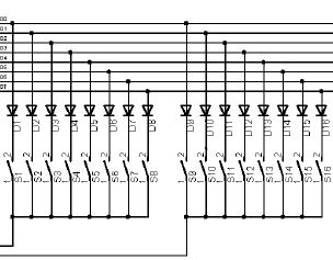
 To read the key contacts, we use a decoder circuit and a diode matrix. The decoder circuit forms the link between the MIDI mainboard (which may be the main board of the Small-Midi or the main board of the BIGMIDI) and the diode matrix.
A diode matrix is a circuit in which diodes are arranged in groups of eight diodes whose cathode is connected to eight key contacts. This group goes up to 64 positions: so 8 groups of 8 diodes, each diode with its cathode connected to a key contact.
The opposite of the key contacts is the key contact rail, which is now divided into pieces, so that now the split pieces include a range of 8 keys.
The microcontroller of main board each time gives a signal to each decoder circuit in the MIDI system with the message, “Now it’s your turn to pass the keystrokes”. The identification of each decoder circuit for the microcontroller is accomplished by giving each decoder circuit a unique “address”.
The decoder circuit now gives each group of 8 switches, a clock signal. At the moment there is a clock signal given from the decoder circuit the microcontroller read the state of the switches via the data bus D0 … D7.
Each matrix of 64 switches (and diodes) is done 8 times: So 8 clock signals, and each clock signal confirmes eight switches gives 64 positions.
Note: Read instead of key contacts also the contacts of the switch register.